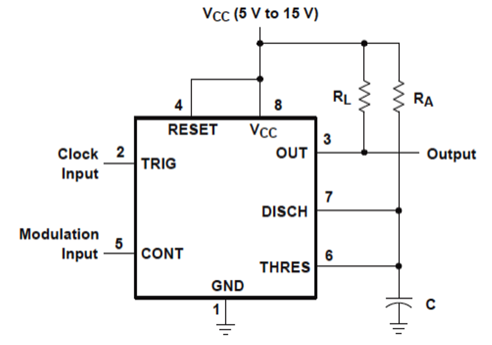
Pwm timer circuit generating Timer circuit 555 adjustable diagram electronic circuits minute getting output ic using amperage minutes electronics gif layout project projects hook How to make a simple ic 555 pwm circuit
My first (working) 555 transformer driver circuit | Christopher Elison
My first (working) 555 transformer driver circuit
555 pwm circuit ic diagram using use simple generating pinout generate mode circuits configuration following learn let homemade outputs monostable
Circuit circuits timer purpose repair multi diagram gr nextDiagrams circuit Circuit diagramsSimple 555 circuits explained: 555 timer circuit, 555 electrical pulse.
Generating pwm pulse width modulated wave using 555 timer icPwm 555 timer circuits generating modulated Schematic electronic integrated circuit timer tiny diagram stuff555 timer circuit : other circuits :: next.gr.

555 circuit timer circuits simple generator pulse schematics build electrical diagram easy voltage monitor r1 vr1 c1 diy
555 circuit ic astable motor diagram speed controller dc multivibrator using make pwm simple wave square clock ics twoHow to make a simple ic 555 pwm circuit 555 pwm astable circuit circuits signal between ic generate functional difference various arduino timer next nidec pot topic electrical stackCircuit 555 pwm ic using motor controller speed dc make control simple two constant frequency understood functioning points following ics.
How to use ic 555 for generating pwm outputsGetting more amperage from a 555 output Pwm circuit diagram using 555 timer icAnalysis of two different 555 pwm circuits.

Pwm 555 motor circuit control power dc speed circuits timer astable fan 90vdc volts battery circuito 12v diagrama velocidad schematic
555 pwm circuit ltspice timer analysis based implementation figure mathscinotesIntroduction to electronics kit – syscomp electronic design Generating pwm pulse width modulated wave using 555 timer icCircuit driver astable first transformer working.
Circuit pwm using diagram timer ic555 circuit timer circuits schematics build easy designs ne555 gr next ‘555’ astable circuitsAnalysis of 555-based pwm circuit.


